SLICE alignment workflow
Purpose
 |
Use the SLICE alignment workflow to adjust the position of the light sheets so that they intersect with the focal plane of the detection objective. Proper alignment is necessary to achieve sharp, in-focus images. SLICE system alignment enables you to get crisp focus at a single Z plane. Crisp focus at different Z planes requires proper system alignment in conjunction with an optimally adjusted offset setting to compensate for refractive index differences throughout the sample. |
You will likely need to adjust the offset as you navigate to different locations in a microscopy sample to achieve good focus. Refractive Index (RI) compensation mapping enables you to record the optimal offset position at different locations of the tissue sample and an RI compensation map is required for acquiring a Tissue Scan. However, if you are just looking at the sample live, you can manually adjust the offset as needed in the SLICE Light sheet panel.
When to run the SLICE alignment workflow
We recommend aligning the SLICE microscope system:
-
Following a regular schedule; many laboratories and core facilities establish schedules for light-sheet alignment.
-
After moving or inadvertently jostling the microscope.
-
If 3D image-volume reconstructions show signs of image-tile misalignment.
-
After installing or removing microscope hardware.
Watch the SLICE alignment workflow in action
SLICE alignment procedure
Before you start
-
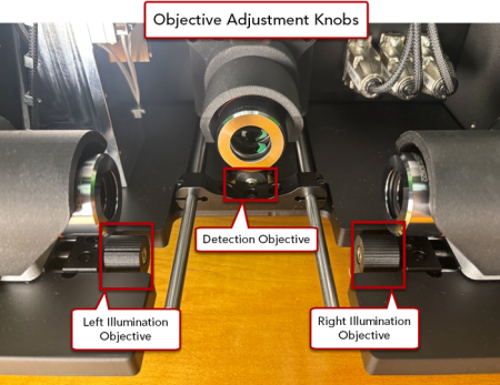
Remove the Refractive Index (RI) Media Tray from the microscope (leave the RI Media Reservoir in place)
-
Removing the tray provides access to the detection objective adjustment knob (center) and the left and right illumination objective knobs.
-
Locate the Alignment Mirror that was included with the SLICE system. You'll notice that the mirror looks scratched or may appear filmy or dirty. These semi-random lines etched into mirror are used for evaluating and optimizing focus in the light-sheet alignment process; we refer to them as alignment marks in these instructions.
Procedure notes
-
Move forward and backward in the workflow by clicking and
-
Helpful instructions are included in each step of the workflow.
-
Throughout this procedure, use the software joystick to move the stage. Adjust the slider to reduce the step size as needed to enable fine stage movements for precise positioning of the mirror alignment marks and light sheets in the field of view.
-
As you move through the workflow, the light sheet controls will automatically adjust as needed for each step.
-
When the alignment workflow is started, Live crop will be automatically turned off. To use Live Crop after completing the SLICE alignment will require users to re-do the configuration.
 Click SLICE Alignment on the Advanced ribbon to get started.
The SLICE Alignment workflow panel will be displayed on the left side of the main window.
If the workflow does not launch after you go to the Advanced ribbon and click SLICE Alignment, it is likely that the Neutral density filter Neutral density filter has not been configured. Follow this procedure to configure the Neutral density filter so that it is automatically selected when the SLICE alignment workflow starts.
SLICE alignment workflow steps
-
Attach Mirror
-
The stage moves to the load position.
Attach the Alignment Mirror to the microscope stage: Tilt the mirror slightly and approach the magnet mount from below to engage one rod with the mirror, then rotate the mirror to engage the other rod. The magnet is strong and the Alignment Mirror should click into place easily. (See a diagram here)
Note that the Alignment Mirror is designed to attach in the correct orientation only.
-
Click to progress in the workflow.
-
-
Start left sheet alignment
Turn on the left light sheet and bring the mirror into the field of view.
 Click to expand.
It is ok if the alignment marks are not in focus at this step.
-
Click to enable the left light sheet.
-
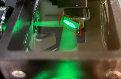
Using the Software Joystick, move the stage in Y and Z to submerge the mirror into the RI medium it is roughly centered on the laser path (see image below).
-
Move the stage in X until a portion of the alignment marks are in the field of view (in the BrightSLICE software window).
-
In order to see the alignment marks, you may need to click or adjust the white point in the Camera Histogram panel.
If the image is saturated and camera histogram appears cut off on the right side, adjust the Camera Settings to reduce the Exposure to 17 ms and the Gain to 100.
-
After the first time this alignment workflow is run, you can click to get the alignment marks into or close to the field of view.
-
It is ok if the alignment marks are blurry.
-
-
(Optional) If there is a rolling line pattern in the field of view, you can adjust the camera exposure time to minimize the rolling effect:
-
If there is a bright rolling pattern, decrease the exposure.
-
If there is a dark rolling pattern, increase the exposure.
Adjusting the rolling pattern is not necessary. It will only be seen during alignment and will not affect the alignment results.
-
-
-
Find center in X
Find the center of the alignment marks on the Alignment Mirror.
Click to expand.
It is ok if the alignment marks are blurry for this step.
-
Find the small red center mark (a circled +) and move the stage in X to align the left edge of the camera feed with the center mark.
In other words, align the border between visible light and solid black with the small red center point indicator in the BrightSLICE window.
Click to record the location.
-
Do the same for the right edge: move the stage in X to align the right edge of the camera feed with the center mark.
Click
Once both edges have been set, the center point between them is calculated and the stage automatically moves to line up the center of the alignment marks with the center mark.
-
-
Translate Detection Objective
Physically adjust the knob under the detection objective so that its focal plane intersects with the left light sheet. Use the center knob under the RI Media reservoir to fine tune the detection objective position.
 Click to expand.
This step includes sub-steps. The illumination for each step will automatically adjust.
-
Sub-step A: Adjust the detection objective position, using the knob below the detection objective underneath the center of the SLICE microscope. The goal is to achieve crisp, clear focus on the alignment marks in the center of the field of view, where the red center mark is located. The knob will turn left and right.
The focus on the right and left sides of the field of view will become blurry. There isn’t an exact line of perfect focus; aim for the image to be balanced in the field of view, with the clearest focus near the center mark.
-
Sub-step B: Adjust the stage position to center the light sheet as follows:
-
Move the stage in X to find the light sheet, which will look like one non-continuous vertical bright line. The light sheet may initially be out of the field of view.
-
Adjust the stage position in X to position the light sheet over the center mark.
If the light sheet line is too broken to see well, move the stage in Y until you find a more continuous line (where there are fewer etched lines on the mirror).
-
-
Fine-tune the alignment by iteratively switching between sub-steps A and B to get clear focus on the alignment marks at the center mark at the same time as the light sheet is positioned at the center mark.
-
-
Adjust left sheet Y center
Adjust the Center setting in the SLICE Light sheet panel, Left Sheet Controls pane to center the light sheet vertically in the field of view.
Note that the height of the light sheet will automatically adjust to the lowest setting (1) when you enter this step of the workflow.
-
Translate Left Illumination Objective
Focus the left light sheet by adjusting the position of the left illumination objective: Physically turn the knob below the left illumination objective underneath the left side of the SLICE to make the light sheet as thin as possible and in sharp focus.
Note that the knob turns forward and backward.
-
Balance illumination left
Balance the left sheet illumination in the field of view.
Click to expand.
Adjust the light sheet so that it is thinnest in the center of the field of view and is equally thick and blurry at the edges of the field of view.
-
Move the stage in X until the light sheet is close to, but not on, the left edge of the field of view. Leave a little space between the edge and the light sheet.
-
Click
-
Take note of how blurry the alignment marks are.
-
Click and then to see if the light-sheet thickness is equivalent. If one side is thicker than the other, click the button to go to that side and turn the left illumination objective knob to get it a little thinner.
-
Keep going back and forth, comparing and adjusting as needed, until the light sheet is thinnest in the center of the field of view and is equally thick at the edges of the field of view.
-
Click to verify that the center is in focus
-
-
Start right sheet alignment
Adjust the right light sheet so that it intersects with the focal plane of the detection objective.
Click to expand.
This step is made up of 2 sub-steps. The illumination for each step will automatically adjust.
-
Sub-step A:
-
Move the stage in the X direction to bring the light sheet into the field of view. Initially, the light sheet may be out of the field of view.
-
Using a small step size, nudge the stage in X to position the most in focus part of the alignment markings over the center mark.
-
-
Sub-step B:
Adjust the Offset setting in the SLICE Light sheet panel, Right Sheet Controls pane, to position the light sheet over the center mark.
-
Fine-tune the adjustments by iteratively switching between sub-steps A and B to position the light sheet at the center mark and get clear focus on the alignment marks at the center mark at the same time.
-
-
Adjust right sheet Y center
Adjust the Center setting in the SLICE Light sheet panel, Right Sheet Controls pane to center the light sheet vertically in the field of view.
Note that the height of the light sheet will automatically adjust to the lowest setting (1) when you enter this step of the workflow.
-
Translate Right Illumination Objective
Focus the right light sheet by adjusting the position of the right illumination objective: Physically turn the knob below the right illumination objective underneath the right side of the SLICE to make the light sheet as thin as possible and in sharp focus.
Note that the knob turns forward and backward.
-
Balance illumination right
Balance the right sheet illumination in the field of view.
Click to expand.
Adjust the light sheet so that it is thinnest in the center of the field of view and is equally thick and blurry at the edges of the field of view.
-
Click
-
Take note of how blurry the alignment marks are.
-
Click and evaluate the light-sheet thickness on the left and right sides. If one side is thicker than the other, click the button to go to that side and turn the right illumination objective knob to make it a little thinner.
-
Keep going back and forth, comparing and adjusting as needed, until the light sheet is thinnest in the center of the field of view and is equally thick at the edges of the field of view.
-
Click to verify that the center is in focus.
-
-
Remove mirror
The stage will automatically move to load position and you can remove the alignment mirror from the microscope stage.
When finished, click
Save key settings to color channels
Overview
Once the SLICE alignment workflow is complete, we recommend that you save the Center and Offset settings, for both left and right light sheets, to the preset for each color channel using the Multichannel Control panel.
You'll save these values to each channel preset.
Procedure
-
Immediately after completing the SLICE alignment workflow, find the Left sheet controls and Right sheet controls panes in the SLICE Light Sheet panel and record the settings for:
-
Center
-
Offset
-
-
 In the Multichannel Control panel, check to make sure that all color channels have been enabled for imaging following these instructions.
 -
One by one, save the Center and Offset settings to the multichannel control preset for each color channel as follows:
-
Click one of the color channels in the Multichannel Control panel to activate the preset for that color channel.
-
Verify or adjust the Center and Offset settings for both the left and right light sheets in the SLICE Light Sheet panel.
-
Save the preset by clicking the Save button near the bottom of the Multichannel Control panel. The words on the button will reflect the selected color channel, for example for the red channel.
If you forgot to save settings before moving on to a different channel, it's not too late to save the settings. Click to open the Preset Saving Options window and click the Save button for the color channel that you initially forgot to save.
-
Repeat for all color channels that are enabled.
-