Change image display panel (3D)
Purpose
 Use the Change image display panel to specify how you want to view images.
- Image-display settings made using these controls affect the active viewport. They are applied to display of the image currently in the viewport as well as that of images moved into the viewport later in your session. The settings do not persist when you close and re-open MicroDynamix software.
- There are two views available: 3D Volume and Image Slice, which displays a single plane. You can trace using either view. The options available depend on the view selected.
To view the Change image display panel
When you open a file in MicroDynamix software, the Change Image Display panel will be active.
|
|
Open the panel at any time by clicking the Tracing button on the MicroDynamix toolbar, then clicking the Image button in the Tracing window |
3D Volume display options
These options are available when 3D Volume is selected in the Display Image as section of the panel.
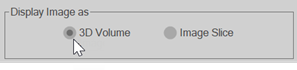
Image stack settings
-
Show surface as (drop-down menu)
-
Min projection: Recommended when the image foreground is brighter than the structures (e.g., brightfield images).
-
Max projection: Recommended when the image background is darker than the structures (e.g., fluorescence & confocal images).
-
Alpha composite: Adds 3D depth and more detail.
If you perform any image adjustment on a projection (max/min projection, or deep focus), you'll need to toggle the projection off and then back on in order to refresh the projection image.
-
-
Partial projection (check box): Check the box to display a subset of the data in X, Y or Z. This can be helpful in visually dense and/or complicated images.

-
Use the slider on the left to navigate the portion of the image to display (click the image to view a short demonstration).
-
The Center position and Thickness of the partial projection display you specify using the slider is reported in the Image stack settings portion of the window.
-
-
Clip tracing (check box): When partial projection is active, you can check the box to Clip tracing so that the display of traced structures and/or markers is clipped to match the portion of the image being displayed.
- Visual Density: Move the slider to control the image-data density that is displayed. Slide left to display the image at lower resolution and maximize software response. Slide right to increase the image-display resolution.
Image Display Transparency
Note that image transparency settings are applied to all color channels in multi-color channel images.
| Simple |
Click the Simple radio button and adjust the transparency using the slider. Simple transparency is applied evenly to the image. |
| Intensity Based |
Click the Intensity Based radio button and the Map button to specify transparency settings for dark, midrange, and bright intensity values in the image. Click Done to apply the settings or Cancel to exit without applying the settings. |
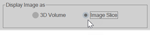
Image Slice display options
These options are available when Image Slice is selected in the Display Image as section of the panel.
3D slice scroll panel
The 3D slice scroll panel opens when you display images as an Image Slice.
.
- Check/uncheck XY, XZ or YZ to display/hide slices (planes).
- To move along an axis, drag the slider for that axis OR click a slider and use the PageUp/PageDown keys to move one plane at a time (click to view a short demonstration).

Image Slice Settings
-
Clip Tracing on Slices Click to hide the display of tracings on all slices (planes) apart from the one selected.
-
Click a radio button to select a slice (see previous bullet).
Image Display Transparency
- Drag the slider to display the image with even transparency across intensities (simple transparency).
Slice Borders
- Show Border Check/uncheck to toggle display of a box around the image slices
- Use the Line Color color picker to select a color for the slice borders.
- Adjust the Thickness slider to set the line weight for the slice borders.
Options available in both views
Bounding Box
-
Show Bounding Box: Check/uncheck to toggle display of a box around the image.
-
Use the Line Color color picker to select a color for the bounding box.
-
Drag the Thickness slider to change the weight of the lines that make up the bounding box.
Undo Changes button: Click to discard the image display settings.
Adjust Image Data button: Click to open/close the Image Adjustment panel that includes options for image-data adjustment.