Track workflow > Setup Worm Detection and Tracking > Detection panel
Detection panel
Purpose
The Detection panel contains settings and commands for adjusting and testing worm detection parameters.
This step is for adjusting worm settings only. To implement custom detectors for objects other than worms, see Use Custom Detector.
Get Started
-
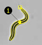
Click a few worms to define a size range. The worms are displayed with an overlay model.
-
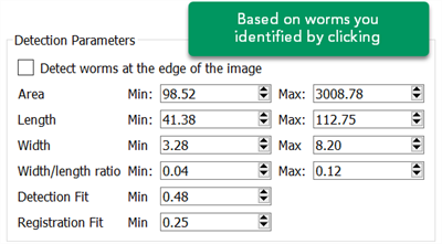
The Detection Parameters are then set based on the worms you identified.
-
Click to obtain a preview of the detected worms in the window.
- If you're not satisfied with the results, click more worms in the window to modify the parameters.
- If you're satisfied, use the Tracking panel to set up tracking parameters.
Commands
Use this command to test worm detection on a single field of view according to the parameters set under Detection Parameters. Worms that do not conform to these parameters are not detected. Parameters can then be adjusted and re-tested as desired.
Detect worms AFTER clicking worms in the current frame to identify a baseline size range for the detection.
Deletes models of detected worms.
Remove the model of a worm that you don't want to track
- Click
 Select in the main toolbar.
 - Click the unwanted worm to select it.
- Press Delete on the keyboard.
Manually add a worm that wasn't detected
Sometimes a worm fails detection because its shape does not conform to the detection parameters or it is overlapping itself.
Rather than reset the parameters, trace the worm manually:
- Click
 Manual Tracing in the main toolbar.
 - Click along the worm's centerline from head to tail to draw the worm.
- Right-click at the tail to end the drawing. An green overlay model is placed over the worm.
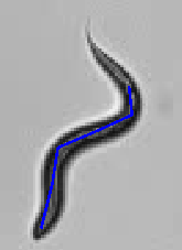
If you right-click away from the worm, even slightly, the model will be incorrect. See an example of an incorrect model here: 
Detection Parameters
Detect worms at the edge of the image: If checked, worms touching the edge of the image are included in the detection.
Area Min/Max: Minimum/maximum area of valid worms.
Length Min/Max: Minimum/maximum length of valid worms.
Width Min/Max: Minimum/maximum width of valid worms.
Width/length ratio: Minimum/maximum width to length ratio of valid worms.
Detection fit: Minimal degree of fit between newly detected worms and image (i.e., the degree to which the contour of the model aligns with the contour of the worm binary image).
Registration fit: Minimal degree of fit between registered worms and image. The value is typically lower than detection fit because worm registration occurs in complex tracking scenarios (e.g., entanglements or occlusions) where the fit between the model and image is usually lower.
Advanced
Detection frequency: WormLab regularly performs an image-wide detection sweep to detect new worms entering the field of view. This setting determines how often this detection process is performed. A higher number of frames between detection increases processing speed, but delays the detection of worms entering the field of view.
-
To restrict tracking to worms selected manually, set the frequency to 0 (zero).
Length Fitting: The default worm model assumes that worms maintain a constant length. Selecting this parameter activates length elasticity with the assumption that worm length is variable.
Length Fitting is useful when the change in worm length must be captured accurately or when detection accuracy of the worm extremities is insufficient.
Width Fitting: Systematically adjusts worm width along the length of the worm. Selecting this parameter will decrease processing speed.
Use Whole Plate Mode: The whole plate tracking mode uses a different model designed for low magnification and a large field of view.
-
For low resolution, worms typically only occupy a few pixels in the image, so accurate worm shape or interaction interpretation is not possible. In this mode, you sacrifice accuracy and tracking robustness for an increase in processing speed.
-
Notably absent from this mode is tracking robustness to worm interaction and self-overlap. For example, when two worms touch one another, WormLab software drops their associated tracking, resuming it only when the interaction ends.
-
Predominant direction: If you know the predominant direction that you expect the worms to move, select it from the pull-down. This information will assist WormLab software in assigning heads and tails to worms and is especially useful with lower magnification/resolution data. Note: If the predominant direction is unknown, the detection does not take into account any directional information and will rely on the Width Extremity—Balanced—Bending Extremity slider to determine head and tail assignments.
-
Click to see the results of the head and tail assignments without having to complete tracking.
-
-
Width Extremity—Balanced—Bending Extremity slider: Drag the slider to determine the relative influence of extremity width or bending in detecting heads vs. tails.
Worm Shape
Fitting iterations: The number of iterations used in the worm-fitting process. With very big worms or high-magnification images, you may need to increase this number.
You may need to increase this value if you have a sequence of low frame-rate images or worms that move unusually fast.
Spinal axis sample: The number of points used to describe the worm median axis. Reducing the number of points increases processing speed. We recommend a minimum value of 31.
Enforce width uniformity: When enabled, this option maintains a uniform width profile along the worm body. This option is especially useful when dealing with low resolution images where the worm radius is less than 7 or 8 pixels. Note that this mode does not allow automatic detection of the head and the tail. If Width Fitting is enabled, WormLab attempts to fine-tune the width profile of the worm while maintaining the uniformity of the main body. If the fitting is successful the head and tail can theoretically be distinguished from one another automatically.