Image adjustment panel
Overview
The Image Adjustment panel enables you to change how the current image looks on screen. You can save these adjustments with the image if you choose; you'll be prompted to decide when you close the file or exit the software.
In images that contain more than one color channel, you can also use this panel to select an individual color channel before tracing/detecting structures; to associate traced/detected structures.
|
Click the Adjust button on the The Image Adjustment panel is a dockable window; you can dock it within the main BrainMaker window or float it elsewhere on your display. |
Histogram
The histogram shows both a bar graph of the image data and a line that represents how the data set is mapped into a display image. 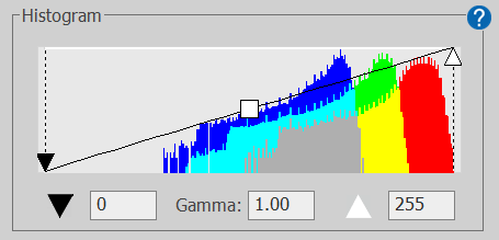
| X-axis | Y-axis | |
|---|---|---|
| Image-data bar graph | Pixel-intensity value | Number of pixels |
| Mapping into display image | Pixel-intensity value | color value (black is 0, white is 255) |
You can adjust image appearance by typing values into the boxes below the histogram or dragging the controls on the histogram:
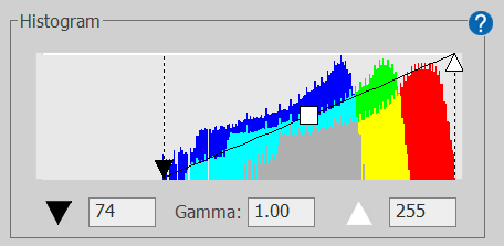
- Black point: (black triangle) The black point is the pixel intensity that defines the lower end of the intensity/color mapping range. In the histogram above, there are no pixels at the lower end of the X-axis, so it may improve image display to drag the black point to where the bar graph shows that image data are present:

- Gamma: Drag the gamma control (or type into the box) to adjust color mapping intensity in a non-linear fashion. This effectively emphasizes either the darker (gamma ≤1) or lighter (gamma ≥1) pixels in the image.
- White point: (white triangle) The white point defines the upper end of the intensity/color mapping range. Similarly to black point adjustment, you may want to drag the white point to where the upper pixel intensity value has associated image data.
Bit depth drop-down menu
Select a value from the drop-down menu to view the image at a lower bit depth.
-
This option is available for images with a native bit depth greater than 8.
-
Reducing the bit depth of an image (intensity/color mapping range) may make it easier to adjust the black and white points.
Display
Color-channel table
Color channels present in the image are shown in a table, with one row for each channel:
-
The first column in the table lists the channel name.
-
The second column shows the selected color representation for the channel. Click the color to open the color changer and select a different color if desired.
-
To view more options for color representation, click the Show Options button and clear the checkbox for Use Simple Color Pickers when selecting colors.
-
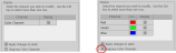
- To display/hide a channel, click to check/clear its Display check box.
- If you select a single color for display in images that contain more than one color channel, any structures that are traced or detected using BrainMaker software will be assigned to that color channel.
- Conversely, if all color channels or more than one color channel are selected for display, structures traced or detected will not be associated with a specific color channel.
Other Display controls
-
Apply changes to stack: Check the box to apply changes to each image in the image stack. When the box is cleared, changes are applied only to the current image.
-
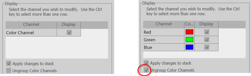
Ungroup Color Channels: Check the box to list each color channel in multi-color channel images and enable individual color channels to be selected and/or modified.
-
Apply to images checked in Image Organizer: When the box is checked, changes are applied to all images in the Image Organizer selected with a check-mark.
-
You can display either Brightness and Contrast or Gain and Offset controls. To choose:
-
Click the Show Options button to show the Display Options panel.
-
You can choose to Work with either Brightness/Contrast controls or Gain / Offset controls by clicking the corresponding radio button.
-
Buttons
-
Reset: Resets the image to its original settings up to the last save.
-
Default: Sets the Black Point to 0 and the White Point to the highest value available for the image type.
-
For an 8-bit image, the highest White Point value is 255.
-
For a 12-bit image, the highest White Point value is 4095.
-
-
Optimize: Sets the black and white points to the lowest and highest appropriate values, respectively.
-
Show Options / Hide Options: Click to show or hide Display Optionsand Optimization Options.
Display Options
[These controls become visible when you click the Show Options button.]
-
Show Luminance: Check the box to calculate luminance from color images (when possible) and display it on the histogram. Note that this is only available if the channels are grouped.
-
Always ungroup Color Channels: Check the box to ungroup color channels when opening images.
-
Use Simple Color Pickers when selecting colors: Check the box to display a set of colors to choose from for the color channels. Clear the box to enable the selection of additional color choices.
-
Work with: Radio buttons enable you to choose whether to use either Brightness/Contrast controls or Gain / Offset controls
Optimization Options
[These controls become visible when you click the Show Options button.]
-
Optimize images of a stack individually: The default behavior is to apply image-optimization adjustments to the image stack as a whole. Check the box to optimize each image in the stack individually.
-
More: Click to view and/or adjust the settings used for image optimization or reset them to the default values.
Saving image adjustments
| Image Only | Stack | Command | Also Required |
| √ | File>Save as>Image Stack>Stack | ||
| √ | File>Save as>Image | ||
| √ | File>Save>Image Stack>Stack |
Adjust Preferences> Images: Under Save, check the boxes next to: "When writing image files..." "When saving only image display adjustments..."
|
|
| √ | File>Save>Image |
